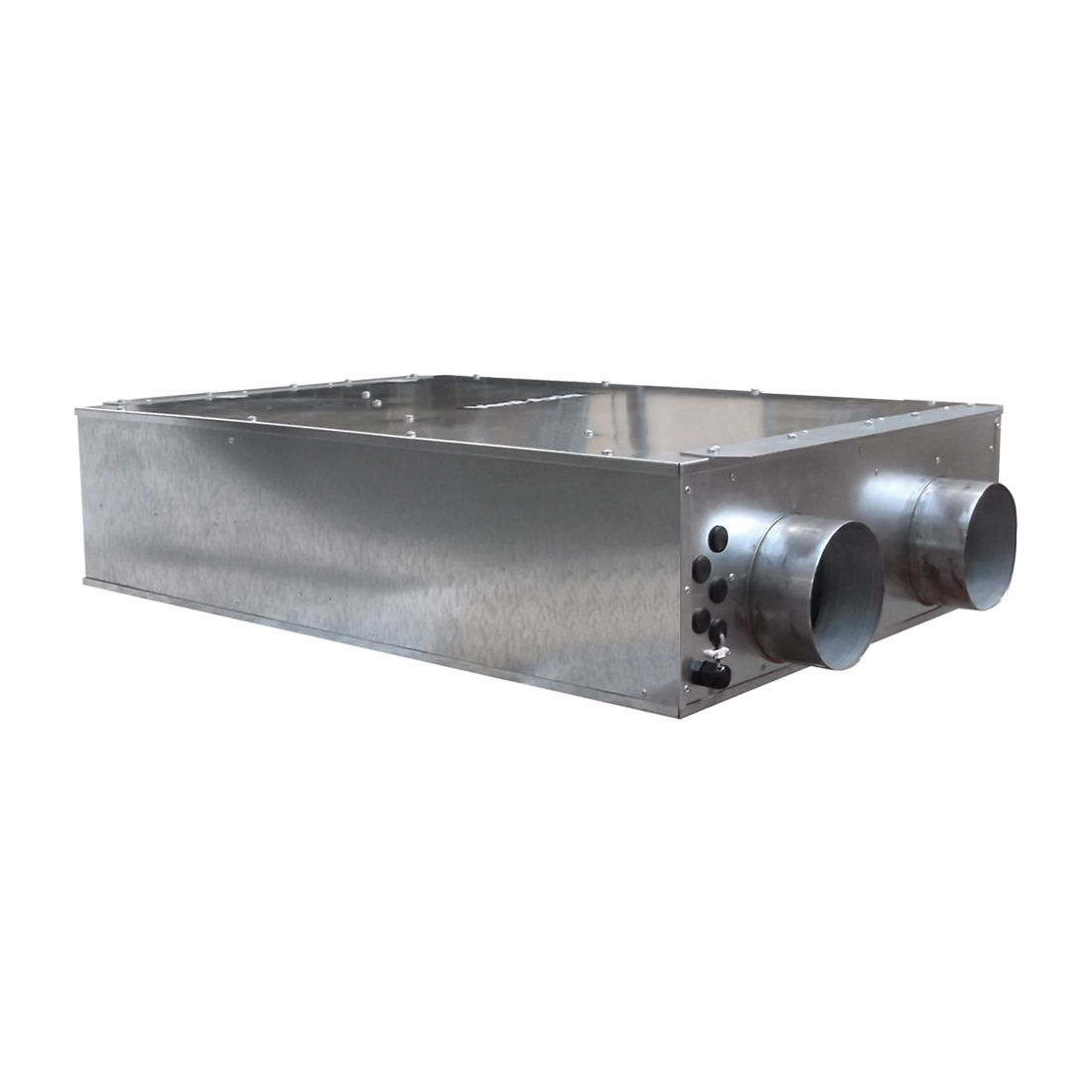
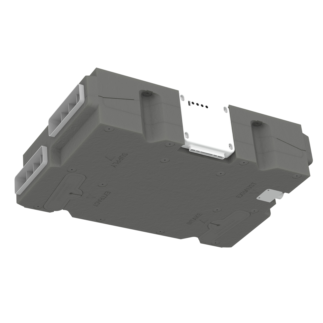
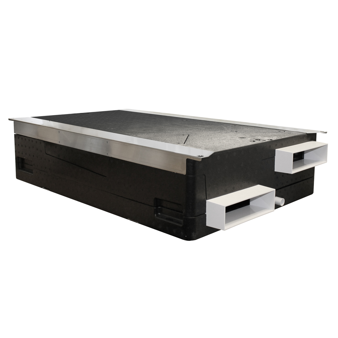
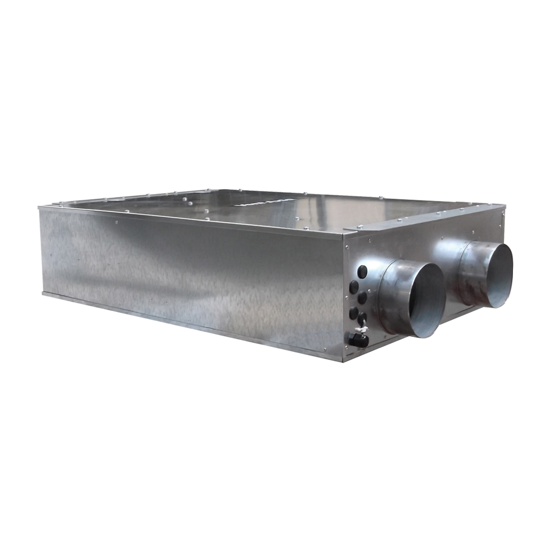
How to install a Vent Axia horizontal 200ZH
Vent Axia 200ZH Wiring Requirements
- 3amp switched spur beside unit
- Digital controller- Comes complete with 15 meter of 6 core alarm cable with a RJ45 connection
- Optional boost switch - 3 core 1.0mm cable from recessed single box to unit(recommended if bathrooms are further than 10 meter
- Further optional include - light switch, vent-wise controller,
Commissioning
- The low and high speed levels can be adjusted using the digital control
- further controls include- night time set speed set back - timed boost- sensor control - humidity sensor control - tempature control - summer bypass control - fault indication - filter indicator
Installation Guide
- Position vent axia 200zh unit on floor or ceiling
- Install wiring for controllers (see bottom of page for further details)
- Install condensation drain from unit to internal or external drain
- Install wall /Soffit vents or roof vents (Minimum 1.5 meter apart) Pipes are 125mm diamater
- Position distribution boxes in the chosen location (proverbially in a central location minimising duct lengths )
- Install silencer (if specified) to air supply distribution box
- Install solid rigid ductwork and between distribution boxes and MVHR unit, (If possible allow for insulated flexible ductwork for final connections of MVHR unit )
- Install radial pipe into the distribution box ,
- Cut to length and install pipe into ceiling plenum, (insure you install rubber seal onto pipe) secure pipe in place with fixing band or pipe clips
Warning! There can be either one or two pipes going from the distribution box to the plenum depending on the required airflow , Always check plan that will indicate 1 or 2 pipes Install insulated rigid or insulated flexible ductwork to external vents Seal all open pipes to prevent debris and moisture ingress
2nd fix
- Trim ceiling Plenums to height of plasterboard (Easier to do before plastering ceilings)
- Install air valves to plenums (slightly open valve by two turns)
- Install all controllers
- Check that condensation drain has been fitted
- Switch unit on and follow the set up procedures
- Check air flow rates and commission system
Initial Design -
-
Pre designed plan - Please follow the plan ensuring the correct number of pipes to each area - Please note the plan is only a guide and you may have to reroute pipe work differently and reposition valves to suit layout of rooms
No Plan - If a design is not possible due to renovation, Retrofit or properties with multiple obstacles simply follow the listed recommendations
We would recommend that you
-
Install 2 x pipes from the distribution box to the room air plenum if air flow requirement exceed 10 L/s or if length over 15 meters
-
Install 2 x pipes from the distribution box to the air extract plenum in the main shower rooms and Kitchen
-
All other areas only require a single pipe from the distribution box to the room air plenum
-
Radial ductwork is suitable to be fitted below your loft insulation providing superior heat retention Insulate any ductwork or Manifold/ Distribution boxes with a minimum of 25mm thermal duct wrap that go above insulation in unheated attic spaces
-
Slim-line manifolds are suitable for installation to concrete ceilings and only require a 100mm service void
-
Position supply plenums approx. 500mm from corner of wall (avoid areas above beds and wardrobes)
-
Position extraction plenums to outside of showers and above kitchen sink (not cooker)
-
Only extract from a room with a open appliance (stove) if there is a supply with equal or higher airflow
-


